Posted on 1 Comment

A3DP Troodon 300 CAD Model Viewer

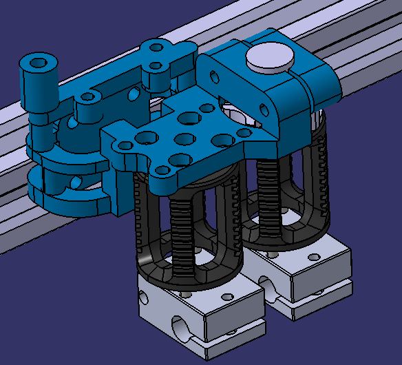
This is the A3DP Troodon 300 CAD Model, it is special sharing version of the model, but is not downloadable.

Inside of the viewer window you can do quite alot but here are some highlights of the most important:

1.) Explode the model (3 Planes Icon)

2.) Measure parts for real-world comparisons (Ruler Icon)

3.) Hide & Isolate Parts / Sub-assemblies to see just what you want

Lastly, I also took the time to rename all of the parts in the design tree (Top-Left corner, look for a Cube & Click on it)

Password to access it is: a3dp <– all lowercase

Posted on 6 Comments

Tuning stepper drivers

Ill start this with saying that if anyone has info on this please come forward as their seems to be very few resources and they are all cryptic. Anyway i have found all the trinamic whitepapers to be very helpful and over the past year hae tested and experimented to the point where i feel i have a decent grasp on how this works.

this is a list of the calculators and guides.

https://www.trinamic.com/support/app-notes/

This is a list of specs that i will keep adding to or if you have any motors you want added comment below and if you have any spec sheets feel free to please comment here or on gihub.

https://github.com/robthide37/components/blob/master/Helpdocs/stepper%20specs

How to use

Posted on Leave a comment

Troodon Klipper Screen Mount (5″ ElecLabs)

This is a guide for printing a turnkey mount for an ElecLabs 5″ Klipper Screen, this is not a full guide for installing the mount. That being said, here is a link to the Klipper Screen documentation. Big shout out to those guys, this screens rocks.

Here is where I used to purchase this screen.

Print Settings:

  • 0.10-0.20 Layer Height
  • 3 perimeters
  • Support: Build Plate + For Support Enforcers
  • See .3MF file so you can simply import my supports & print settings (Speed Conservatively set to 80mm/s, DDE req’d)
  • Print with the Text facing Down & Add a Brim (Not Pictured)

Assembly Tips:

  • Start by removing front Black acrylic panel with existing PanelDue and remove 4 Phillips M3 bolts, save the 4x Phillips M3 bolts for later
  • Make sure you have tested your Raspi Klipper Screen for functionality, if you plug in the DSI cable and nothing happens, you likely have a Type-A cable (Pins on side 1 at one end, Pins on side 2 at other end) but this screen needs a Type-B DSI cable. I simply took a normal Raspi Cam cable, clipped off the blue tag (heat gun to remove and super glue on opposite side) then took some sand paper to expose the pins on the opposite side. If that is too much work for you, just search type B DSI on the Google Machine and purchase one.
  • When you install the screen into this mount, side it in at an angle with the USB port nested in the cutout.
  • Then lineup the top mounting holes and screw in 2 of the longer M2.5 Phillips bolts provided in the kit.
  • Next, gently slide the partial assembly through the backside of the front black acrylic. Re-install 4x M3 Phillips bolts
  • Now slide the bottom piece on and align the holes and install the last two long M2.5 Phillips bolts from the kit.
  • Lastly, there are two holes, at an angle, that are made for M3x14mm bolts, this will securely hold the two halves together.
  • The 2 holes on either side of the mount are for you to design & mount your own tool/flashlight/screwdriver/etc mounts…
  • Finally mount the PI stand off and RaspberryPi onto the mounting studs on the back of screen & plug it in.
  • If you sanded your cable (or bought the correct one) then it will power up, if not nothing will happen.
  • Proceed with running the install commands (from above links) and you should be good to go.

Rather than charging for this before you try it, I would rather use this as an Honor System. I’m more concerned with growth than money but money is a necesarry evil for coninued development. If you found it useful and would like to see more like it, please consider donating to the designer with the “Tip the Designer” button below:

Future Projects I am considering:

  • Troodon Heated Chamber Mod
  • 9mm Z Belt Conversion
  • Actively Heated Above Mounted Filament Drying Box
  • Umbilical Mounts for Troodon Cable Chain alternative
  • Other Top Secret Awesomeness we’re not quite ready to share yet =)
Tip

Posted on 2 Comments

Pressure Advance: The Easy Way, “Just use the new tool”

Linear Advance Calibration Pattern | Marlin Firmware (marlinfw.org)

The tools tab now has native generators on it.

This is a basic guide on making a PA (Pressure Advance) gcode file. I plan on forking the code and changing it to natively generate the gcode for RRF and Klipper, but it’s easy, so I am not making that a priority. Just use the above-linked tools.

  1. Generate the gcode for marlin inputting your settings for the filament and nozzle you are using. You want .005 steps ranging from 0 to .1 for most nozzles and filaments. If your filament is very soft or your nozzle is small, then .2 may be better as a maximum value.
  2. Add a G32 after the G28 in the side panel.
  3. Add a T2000 after the P500 on the acceleration line.
  4. Download and open in notepad, or some other simple editor that does not format text.
  5. Use find and replace to find M900 K and replace it with the respective values:
    1. Klipper is SET_PRESSURE_ADVANCE ADVANCE=
    2. RRF is M572 D0 S
  6. Save the file, making sure the extension is .gcode.
  7. Upload to the printer and print.
  8. Find the line that stays most uniform at the speed changes marked by the top two vertical lines.
  9. Enter the corresponding value in your slicer’s filament gcode override. If slicer does not have that, then enter it into your start code and name that profile for the filament you calibrated.

I found some cool diagrams that show the improvements with Klipper pressure advance compared to regular Linear Advance (LA) and PA with the smooth pressure advance algorithm. With direct drive, it does not matter as much, but with Bowden and high values, Marlin and RRF have a hard time keeping up and end up slowing the print a lot to maintain the max acceleration for the extruder in firmware. So, a stock 300 really needs 1.9 and that doubles print times on RRF. With Klipper, it is not a problem and it does not reduce the acceleration as the extruder hits its ceiling. Instead, it smooths out the max values and extends them slightly to the same end result. You can configure the smoothing time if you really are pushing things, but the stock value is adequate. We do not want to reach the point where we start reducing the effectiveness of the pressure advance. This all is not important if running direct drive since we rarely need more than .1 seconds of Pressure Advance with the Orbiter or most other high-end solutions. I just figured it would be interesting to give some background on what is happening under the hood.

https://github.com/KevinOConnor/klipper/issues/1260
Posted on 4 Comments

Klipper guide for flashing and install

Alex Or is helping by putting a lot of my pictures and information together into a presentation. It should be ready soon, he had me review his draft. We are making a few changes, but it looks great already. It is time to make a video of the flashing procedure, so Jake Allen installed a new board and let me record a remote session of me flashing it for him.

Here is a video showing the basic harness install.

Holger asked for a picture of the pi camera mounting location.

Posted on Leave a comment

Klipper harness install

The klipper harness is assembled with the intent of using the small triangles on the harness to locate the pins.

A rpi diagram courtesy of raspberrypi.org shows the pin numbers here

GPIO - Raspberry Pi Documentation
https://www.raspberrypi.org/documentation/usage/gpio/

The harness comes with a diagram and shows the pin numbers. The main harness, the connector on the right in the below image, has the pin marked with a triangle go to pin number 2.

The harness connector on the left is for the accelerometer, and is not needed for the main install.

Connect the Panel Due harness in the manner that is described in the video below. Be careful of the orientation of the Panel Due plug you remove, and connect the power wires as described.

One of my Patreons is working on a presentation documenting the install, so I will add it when it is ready.